|
Beam Bridges - Design Technology |
|
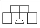
Beam bridges A beam or "girder" bridge is the simplest kind of bridge.
In the past they may have taken the form of a log across a stream
but today they are more familiar to us large box steel girder bridges.
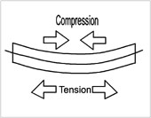
There are lots of different types of beam bridges. Under load, the beam's top surface is pushed down or compressed
while the bottom edge is stretched or placed under tension.
If we imagine that there is an imaginary line running down the centre
of the beam this line remains at its original length while the material
above is compressed and the material below is stretched. This line
is referred to as the neutral axis.
|
||||
Types of Beam Bridges
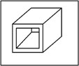
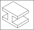
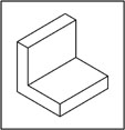
Beams Beams used in buildings may vary in cross sectional shape. Some may be solid or hollow. Below are three different shaped beams. The first beam is a box section, the second an I section beam and the third an L section beam. Solid beams are heavier than hollow beams. Beams like the one's below are given a special cross section for strength and rigidity. They may be as strong as the solid beams but are a lot lighter. We may describe them as having a good strength to weight ratio. |

 |
 |
 |
Reinforced Concrete Beams Concrete beams that are used in buildings as horizontal supporting
pieces above doors and windows. These are called lintels. These
lintels are reinforced with steel rods cast in the concrete. The steel
rods are normally placed below the neutral axis. The combination of
more than one material makes the reinforced concrete a composite
material. The steel enhances the strength of the concrete when
stretched under tension. |
| Task 1. Using card and glue make the three beams above. Test the beams
individually for structural strength and resistance to loads (stress)
in compression and tension. We can achieve this by placing the beams
between either desks or chairs. If weights are hung or placed on top
of the beams we should eventually be able to witness the shape of
the beams altering. It will indicate the points of weakness. They
may fold or bend depending upon how much weight is hung from them.
2. Test each beam with increasingly heavier weights. Whilst hanging the weights from the beams record both the size of the weight and the structural damage if any it has upon the beam. Place these results into a spreadsheet or record your results in a chart with notes describing the changes. You may consider using a newton gauge or clock gauge to test the beams. 3. Once you have completed your experiment explain which beam held the heaviest weights for the longest length of time without folding or crumpling in any way. 4. Explain why this type of beam appeared to be the structurally stronger than the other two? 5. Suggest where this type of beam is used in architectural structures? 6. Using additional card attempt to increase the strength of the beam? Remember too much additional card will make the beam too heavy. It will end up with a low strength to weight ratio. |